
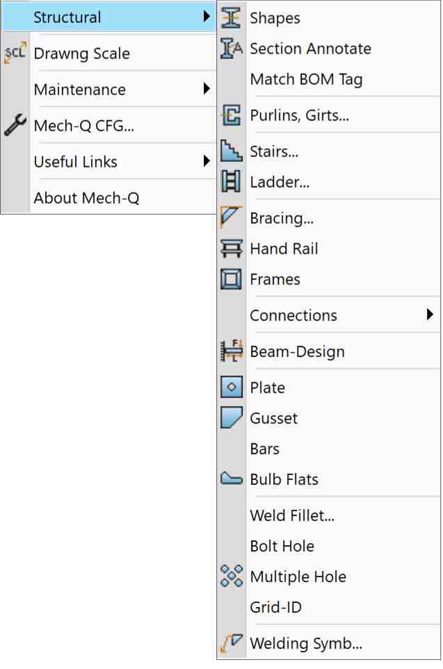
Our Structural Software draws structural steel members, including steel shapes (beams, columns, and miscellaneous), beam connections, stairs, ladders, bracing, hand railing, frames, welding symbols, beam loading designer, and much more.
Steel shapes include AISC, BHP, CISC, DIN, RSA, JIS, IS, Chinese…The module draws both 2D & 3D and generates a weighted auto-BOM. Some modules include auto dimensioning of components to fabrication details. The structural software supports both Metric & English (Imperial) Units.
Steel Shapes & Beams
Our structural software add-on draws steel beams in 2D & 3D, including Auto-BOM with weighted BOM (fully customizable). This structural steel shape routine supports data listing with a pick & match option. Layers are fully customizable. A curved beam option is also available. Annotates shapes and beams as needed.
Main Features:
- 2D & 3D Capability
- Auto-BOM with weighted BOM (fully customizable)
- Data listing, pick & match option
- Fully customizable layers
- Curved beam option
- Annotation option
Standard Steel Shapes and sizes included:
Metric:
- Australian (BHP)
- European (DIN)
- British Standard (BS)
- Canadian (CISC)
- South African (RSA)
- Japanese (JIS)
- Indian (IS)
- Chinese
English:
- US (AISC/ASTM)
- Canadian (CISC)
ASVIC can customize this utility for other standard steel shapes.
Structural Stairs Utility
Structural Stairs Utility will draw stairs to the configuration set by the user. The routine will also draw Single-flight and multi-flight stairs in Front, Plan, and End views and then add the main Dimensions and Stair Data as required. A handrail outline can also be included.
Stringer Detail – With auto-dimensioning for fabrication. Use the program design feature to draw the stairs – then, by simply picking the stairs stringer; it will be auto-detailed for you.
It also includes concrete Pan Style stair tread. The user can control the stair design parameters, including stringer and tread sizes, slope, width, and stair flight configuration.
Main Features:
- Draw Single-flight and multi-flight stairs
- Front, Plan, and End views
- Auto-handrailing
- Several stringer & tread options – With auto-dimensioning of a stringer for shop fabrication
- Fully customizable with full control of the stairs design parameters, including:
- stringer and tread sizes
- slope
- width
- stair flights configuration
- Fully customizable layers
- Easy to use and configure
NOTE: Recognized safety constraints control the configuration of the stairs
Structural Ladders Utility:
The Ladder Utility will draw Side Stepping and Step Thru—ladders – Front, Plan, and End views. The utility can also draw safety Cages and fabrication Details. Auto Dimensioning is included.
Main Features:
- Draw Step-thru and Side-step ladders
- Front, Plan and End views
- Ladder detailing (with auto-dimensions)
- Safety cages optionally added
- Customize layers used
- Fully customizable with full control on all the ladder design parameters.
- Easy to use and configure.
- Structural Hand Railing:
- Customizable sizes, layers & shape
- Welded, “Monowills” and Square tube
- Steel or Aluminum
- 15 types of stanchion
- Optional “kick” plates.
- Several draw options
- Easy to use and configure.
- Several draw view options:
- Run Elevation – Pick two points, and handrail + stanchions are drawn
- Run Plan – Draw an outline poly-line, then pick a poly-line to draw
- Stanchion Front view
- Stanchion End view
- Stanchion Plan view
- 90-deg Bend
- Angled Bend
- Horizontal Closure
- Angled Closure
- Structural Bracing
Other Structural Features
Fully Customizable sizes & layers. Supporting welded, welded cleat, bolted cleat, or bolted straight bracing. Simple to use, draws bracing in 4 easy steps! Fixing options include Welded, welded cleat, bolted cleat, or bolted straight.
Main Features:
- Fully Customizable sizes & layers
- Welded, welded cleat, bolted cleat or bolted straight
- Bracing is drawn in 4 easy steps:
- Select IP 1st point
- Select fixing member at 1st point
- Select IP 2nd point
- Select fixing member at 2nd point
Beam to Beam Connections:
Drawing structural steel beams is easy with our structural software software add-on. Includes several connection types: bolted & moment Plate, angle or double angle cleats. Will draw in plan or front draw views. Customizable layers & connection sizes & design w/ auto-dimensioning to fabrication details. Beam weights calculator and much more included.
Main Features:
- Several connection types: Bolted & moment
- Plate, angle or double-angle cleats
- Plan or front draw views
- Customizable layers & connection sizes & design
- Auto-dimensioning to fabrication details
- Dimensioning style & options to meet most detailing requirements.
- Beam weights calculator
- Several draw options
- Easy to use and configure….
- Beam to Column Connections:
- Several connection types:
- Flexible: Angle seat
- Flexible: Bearing pad
- Flexible: End plate
- Flexible: Angle cleat
- Flexible: Web plate
- Rigid: Welded & erect cleat
- Rigid: Plate
- Plan or front draw views
- Customizable layers & connection sizes & design
- Auto-dimensioning to fabrication details
- Several draw options
- Easy to use and configure
- Structural Welded Frames
- Bevel or Square corners.
- Plan, End view (X) and End view (Y)
- Plan or end draw views
- Customizable layers & sizes
- Auto-dimensioning to fabrication details
- Several draw options
Beam Design Module
The utility is a design tool for calculating stresses and deflections for simple beam cases.
Beam cases Include:
- Simply Supported
- Cantilever
- Propped Cantilever
- Build-in
- Several load cases and load combinations are supported
- Reactions at supports
- Calculated Deflections and Stresses
- Plot of stress and deflections
- Printed Result
- Minimum Steel Sections for the given load cases.
- Several configurations & calculation options…
- Welding Symbols
- Several welding symbols Include:
- Fillet
- Bevel-butt
- Vee-Butt
- Square-Butt
- U-Butt
- J-Butt
- Flare-V
- Flare-bevel
- Plug
- Spot welding
- Seam welding
- Stud welding
- Bead welding
- Surface welding
- Welding note option
- Configurable size & layers
- Several options & auxiliary symbols: Site, all round, leader, intermittent…
- Other modules & utilities included
Steel Shapes included:
Metric:
- Australian : (BHP):Hot Rolled sections, including: UB, UC, PFC, EA, UA, Welded UB & UC and RHS.
- European : (DIN):INP & IPE, HEA & HEB, UNP & UPE, LE & LU, & RHS
- British Standard : (BS): UB, UC, PFC, EA, UA, CHS & RHS
- Canadian : (CISC) : W, WWF, S, M, HP, C, MC, L & HSS.
- South African : (RSA): I , H, Channels, Angles, & RHS.
- Japanese : (JIS): I , H, Channels, Angles, & RHS.
- Indian : (IS):Beams , Channels, Angles, & RHS.
- Chinese: HW, M &N Beams, Channels, Angles, & RHS sections,
English:
- US : AISC/ASTM: W & WT, S, M, HP, C, MC, L & RHS
- Canadian : (CISC):W, WWF, S, M, HP, C, MC, L & HSS